
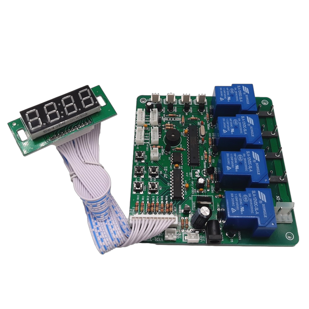
Working Mode
Connect to Bill acceptor Example
Description
|
Input Voltage for circuit |
DC+12V |
|
Input Voltage for device |
Based on Input voltage for device |
|
Standby |
Display shows:00:00, reply: Normal Open (NO) |
|
Max current load |
15A for total |
|
Basic working way |
User inserts coins→ goes to balance→choose device to use by push button start→device start working |
|
Check Balance |
Push a button when stand by |
|
Display |
- Standby: shows 00:00 - Running Time: Shows remaining time
|
|
Insert coins when time is running |
- Credit goes to balance. - Add time after user push button start. |
-
Various mode:
|
Title |
A |
B |
Description |
|
Working way |
01 |
01 |
Only 1 device can work simultaneously |
|
02 |
1-4 devices can work simultaneously | ||
|
Light for button |
02 |
03 |
Lights all the time |
|
04 |
Lights when devices can be used | ||
|
05 |
Lights when devices are working | ||
|
Time Type |
03 |
06 |
Hour: Minute |
|
07 |
Minute: Second | ||
|
Memory |
04 |
08 |
Yes, keeping running after re-power on |
|
09 |
No, standby after re-power on | ||
|
Back to Standby |
05 |
|
|
| |||
-
This item goes with setting manual. If you need to see manual before buying, please contact us for it.
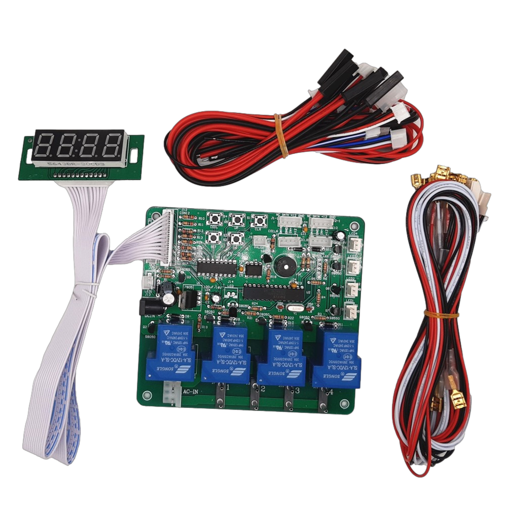
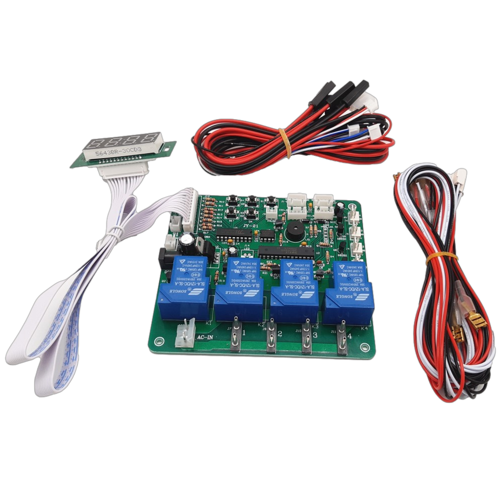
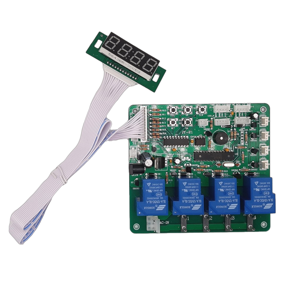
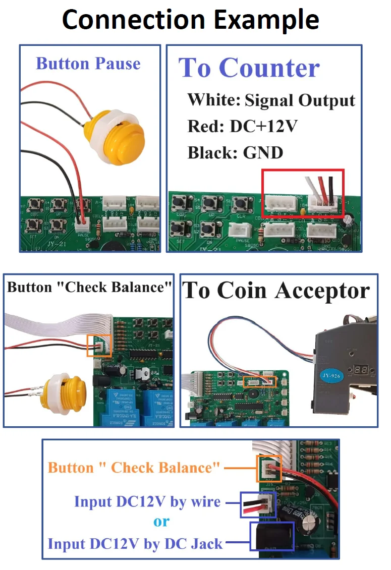
Connection Example
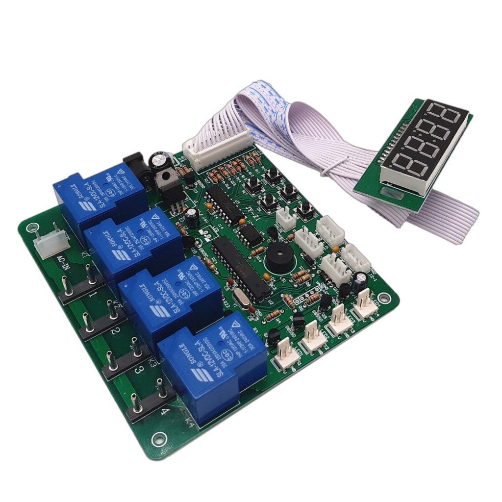
Power to control machine power wire:
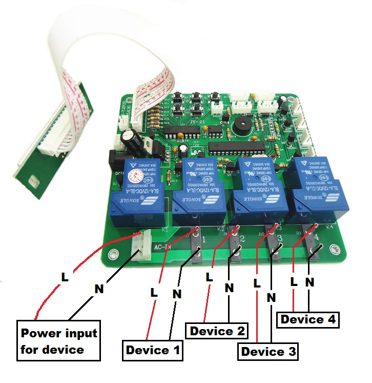
example-1
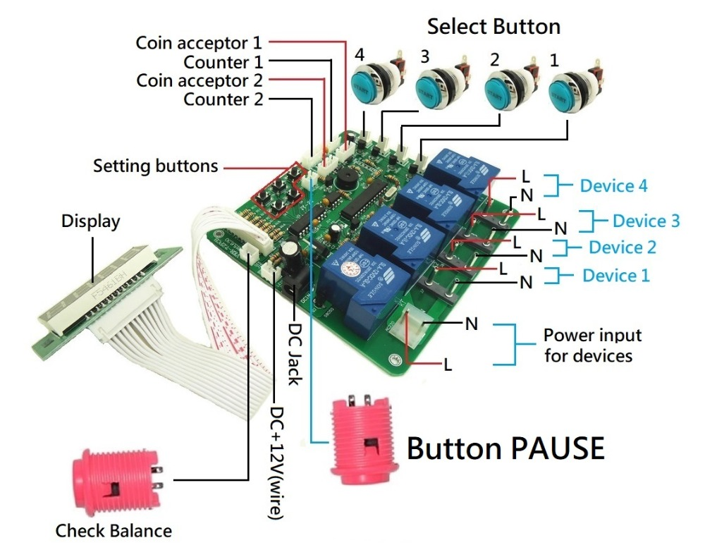


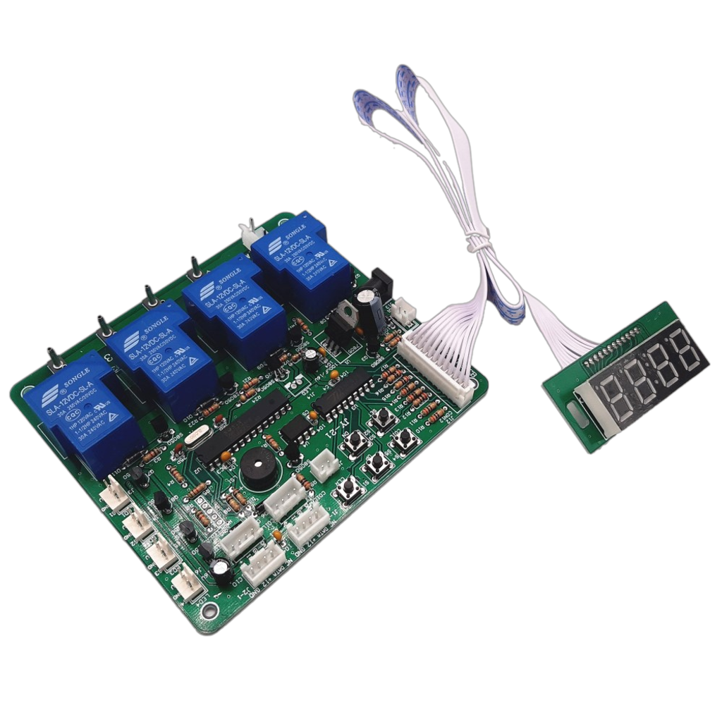
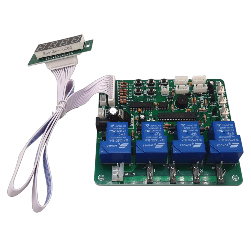
White Lead between main board and display: 60cm
Note:
- For button PAUSE and BALANCE CHECKING, you need to solder wires to buttons